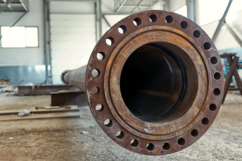
Joints Fail, Not Just Gaskets!
Low bolting torques, over-tight bolt loads, weak bolt material, inadequate bolt/washer/nut lubrication, poor flange design or materials, poor gasket cutting or storage, improper installation, may each and all contribute to seal failure. Only when all the components of the system are working together in harmony can the seal be expected to provide good performance over a reasonable lifetime. The integrity of a safe seal depends upon the selection of correct components appropriate for the application. (Flange, Gasket, Bolts, Nuts and lubricant), careful preparation, cleaning, installation and assembly, correct bolt tightening and loading.
Gasket Sealing
A gasket’s role is to seal the space between the mating surfaces of a flange connection. This is accomplished when the bolt load compresses the gasket to a level of tightness that allows it to fill the gap between the mating faces and fill the small imperfections in the sealing surfaces. With proper flange design and gasket installation, the stress on the gasket will be sufficient to create a barrier between the pressurized side of the gasket and hold it securely in place. All the paths of leakage are effectively blocked between the gasket and flange. However, what if portions of the flange face are damaged? Will the flange leak if used or should the end user replace it? Let’s look at flange face damage and its potential effect on gasket sealing.
Types of Damage
Over time and for any number of reasons, damage can occur to flange faces. Each damaged area will tend to create a potential leak path that the gasket must try to seal. Some common types of flange surface damage, their characteristics and possible causes are listed below:
A. Scratches
This type of damage is narrow and elongated with sharp, shallow bottoms. However, depending on the force that created them, they can be deep. Frequently, this type of damage is created by a sharp object dragging across the flange face. These objects may include the bristles of a wire brush or a tool, such as a chisel.
B. Gouges
These are wide and elongated with blunt, rounded bottoms and are created by a dull object dragging across the flange face. Gouges can be caused by objects—such as a screwdriver, flange jack or chisel.
C. Pits
This damage is usually small, somewhat rounded areas of concentrated material loss created by corrosion. Often, pits occur in clusters or groups.
D. Dents
This type of damage can be sharp or blunt non-elongated areas caused by some form of impact. Dents sometimes result from equipment collisions caused by positioning the mating flanges using cables and rigging.
The most common events that create surface finish damage are indentations that occur from removing previously used gasket material from the sealing surface. Tools, such as chisels or screwdrivers, should be avoided. A brass wire brush is preferred.
Damage Impact
What the damage types have in common is that they reduce the sealing tightness of the gasket against that particular (damaged) area of the flange face. If these defects are small and few, the leak tightness of the bolted connection will not be significantly impacted. If a defect is large (especially across the radial direction of the flange face) or several defects are grouped in a small area, the leakage path can exceed the ability of the gasket to block it, and leakage can occur.
Conclusion
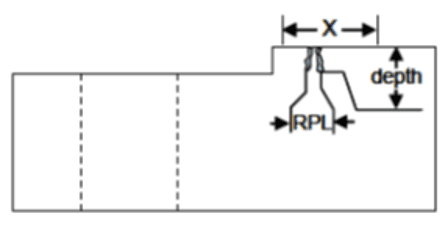
Whether the gasket can successfully seal these damaged areas depends on their size, depth, orientation and number. The question then becomes, how large is too large, or what is the limit on the number of small defects in a single area? Is the flange “fit” to be returned to service? In 2010, the American Society of Mechanical Engineers (ASME) addressed this issue in its standard, Guidelines for Pressure Boundary Bolted Flange Joint Assembly, ASME PCC-1-2010. This standard provides guidance for several important flange considerations. Appendix D of the standard includes information that specifically addresses issues of flange surface condition. Appendix D includes figures and tables that provide guidelines for setting allowable limits on flange face defects. Specifically, it shows how to assess damaged portions of a flange face by taking measurements of the defective areas (see Figure 1 in Appendix to Article – Flange Face Inspection Criteria). With these measurements, Table 1 can be accessed to determine the applicable limit for a particular type of damage. Limits are established by determining the effective length (in the radial direction) and matching it to the depth of the same defect. The respective limit will depend on the type and category of gasket being used in the bolted flange connection.
References
- ASME PCC-1-2010
- ASME B16.5
- ASME B16.47
- ASME B16.20
Appendix to Article – Flange Face Inspection Criteria
Table – D-1M Extracted from ASME PCC-1-2010:

Table D-2 (D-2M for metric) Extracted from ASME PCC-1-2010:
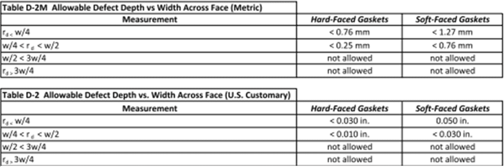
Figure – 1
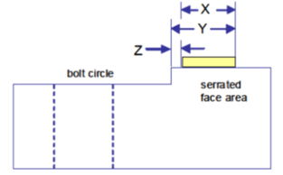
Table – 1: ASME B16.5 Flanges/B16.20 Gasket Seating Parameters “Y” and “Z” (to Determine “X”)
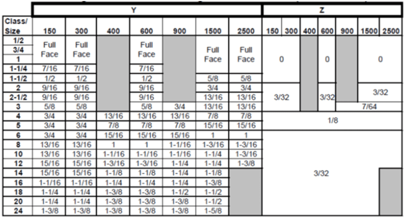
Table – 2: ASME B16.47 Flanges/B16.20 Gasket Seating Parameters “Y” and “Z” (to Determine “X”)
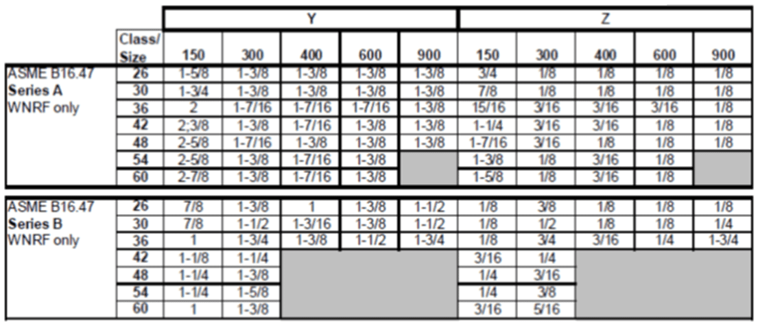
Only imperfections within the gasket seating width, “X” are to be considered as imperfections that can be rejected. The gasket seating width “X” is defined in Figure 1 and Tables 1 and 2.
Table – 3: Maximum Radial Project Length for Various
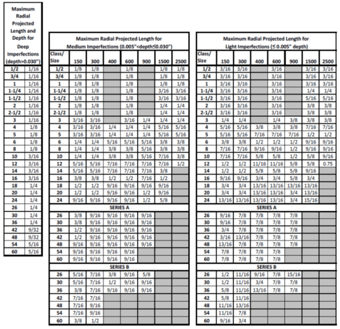 Values shown in the above table only apply with ASME B16.5 and B16.47 flanges using an ASME B16.20 gasket. Protrusions above the serrations are not permitted anywhere on the raised face. Radial Projected Length is only measured within the Gasket Seating Width.
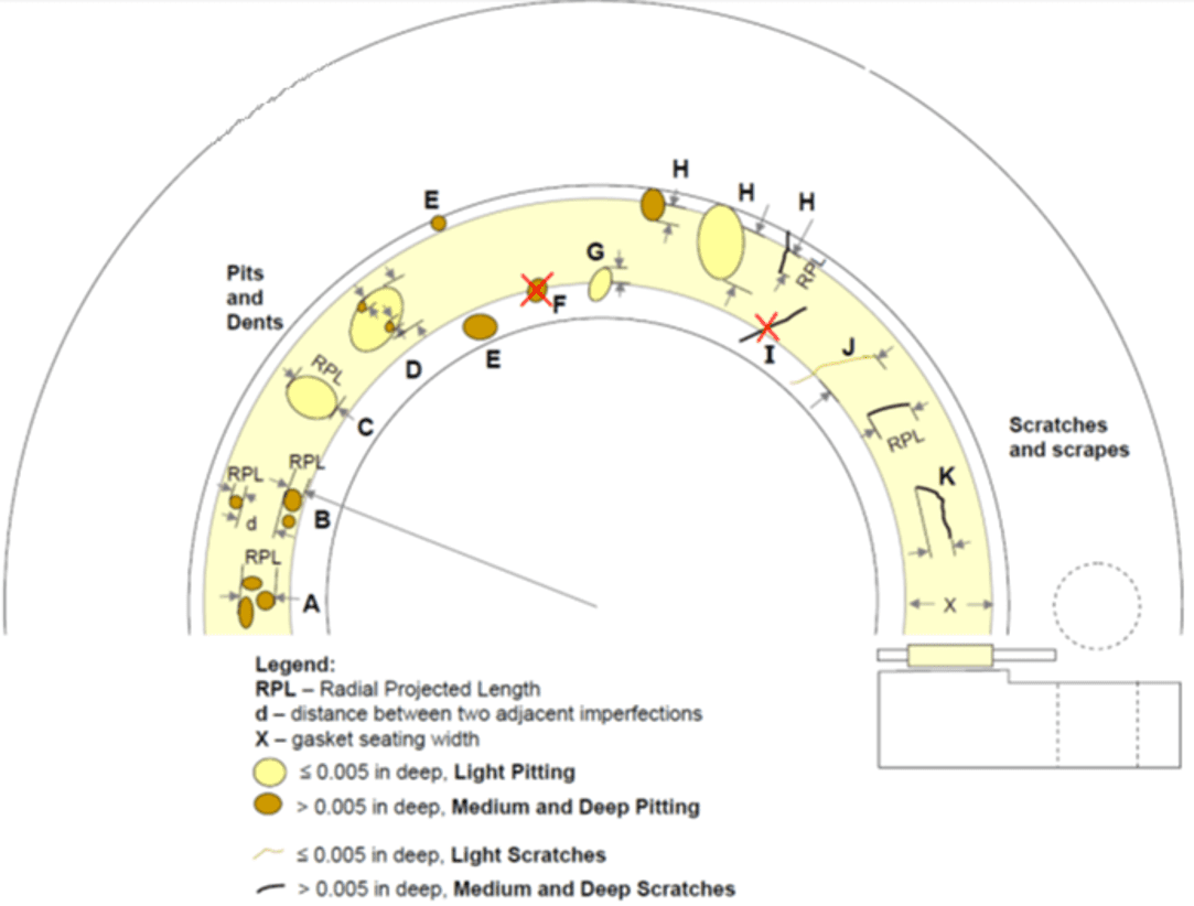
Figure – 2: Representation of the Flange Face that shows defects and illustrates various cases for applying criteria to accept imperfections in Flanges. Protrusions above the SERRATIONS are not permitted.
 Permissible Imperfections in Flange Face finish
The various cases that are illustrated in Figure 2 are described below:
Case – A:
 When two adjacent imperfections are closer than the sum of their individual RPL, they shall be joined together as a single imperfection. The RPL shall include both defects. The RPL and depth of the joined imperfection shall not exceed the values given in Table 3.
Case – B:
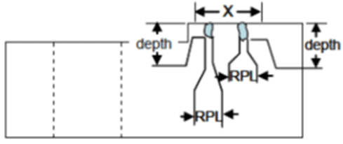 When two adjacent imperfections are farther apart than the sum of their individual RPL, they shall be considered two independent imperfections. The RPL and depth of each separate imperfection shall not exceed the values given in Table 3.
Case – C:
 When an imperfection is characteristic of a grouping of small pits (generally the result of corrosion), and the depth of the group imperfection is less than 0.005” below the serration, and the serration profile is generally maintained, the group shall be analyzed as one imperfection. The RPL of the group imperfection shall not exceed the values given in Table 3.
Case – D:
 When Case A or Case B imperfections are within the boundaries of a Case C imperfection, the Case A and Case B imperfections shall be analyzed independent of the case C imperfection. The RPL and depth of each of these Case A and Case B imperfections shall not exceed the values given in Table 3.
Case E:
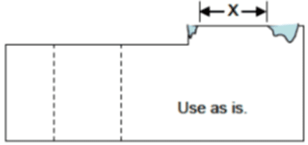 Unless the imperfection is a protrusion, an imperfection completely outside the GASKET SEATING WIDTH (X) is acceptable as is. Only imperfections within the GASKET SEATING WIDTH are evaluated as a rejectable detect.
Case F and I:
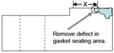 An imperfection crossing the borderline of the GASKET SEATING WIDTH from the inner side of the serrated face and having a depth greater than or equal to 0.005” below the serrations shall have the portion of the imperfection that is inside the GASKET SEATING WIDTH eliminated.
Case G and J:
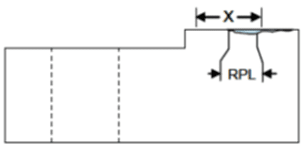 An imperfection crossing the borderline of the GASKET SEATING WIDTH from the inner side of the serrated face and having a depth less than 0.005” below the serrations shall have the RPL measured only with respect to the portion occurring within the GASKET SEATING WIDTH. The RPL of the imperfection shall not exceed the values given in Table 3.
Case H:
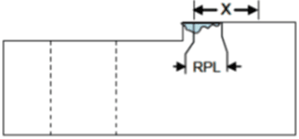 An imperfection crossing the borderline of the GASKET SEATING WIDTH from the outer side of the serrated face shall have the RPL measured only with respect to the portion occurring within the GASKET SEATING WIDTH. The RPL of the imperfection shall not exceed the values given in Table 3.
Case K:
Scratches and scrapes having a depth greater than 0.005” below the serration are evaluated with the same guidelines as other imperfections, Cases A, B and D.
Case L:
A decision to accept or reject the flange shall be taken based on the below-mentioned conditions:
- the RPL of very light scratches and scrapes exceeds the acceptable value in Table 3 (3/4 of GASKET SEATING WIDTH)
- the scratches are the only rejectable imperfection for a flange
- the serrations are maintained
- and the depth of the scratches are less than half of the serration depth
Nirmal Surendran Menon, PMP®, is the author of the book, Valves Made Easy, along with a coauthor, who is an industry expert as well as a project management professional with 17-plus years of experience in the oil and gas/energy facility construction. He currently works as a senior construction manager overseeing the Pipe Pressure Testing and Pipe Cleaning portfolio with an EPC company with a distinguished reputation in the industry. Menon’s interests include pipe integrity, pipe cleanliness, loss prevention, and human factors for process facilities. He has authored 11 articles and two books, and has sustained national and international acclaim in the industry, having been part of major LNG project construction execution in different geographical locations.
Testing and Quality Engineer with experience in driving excellence in creating, editing, and implementing test instructions, quality procedures, and hands-on training in an effort to improve quality and efficiency.

