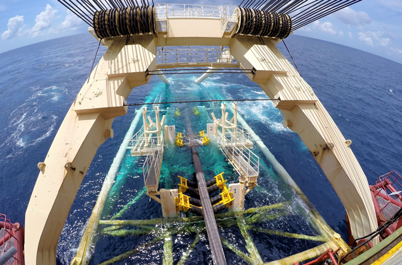
Several methods exist for the installation of rigid subsea pipelines. Some of the better-known ones include: S-Lay, J-Lay, Reel Lay, Surface Tow, Below Surface Tow, Bottom Tow, Bottom Pull, Control Depth Tow Method, Horizontal Directional Drilling and Push-Pull Method.
Of all the methods for pipeline installation, the Reel-Lay method is the one which subjects the pipeline to the most punishment before it is finally laid to rest on the seabed. The pipe is already plasticised during reeling before being sent to site for installation and then subjected to further plasticisation as it is uncoiled, straightened and then laid down to the seabed.
This article provides an overview of the potential failure modes that may occur for the Reel-Lay method of subsea pipeline installation and provides ideas and past learnings for considerations in order to overcome such potential failures.
Reel-lay method of rigid pipeline installation refers to a method of pipeline installation where a rigid pipe is un-spooled from a drum, straightened, tension applied, and then laid over a ramp to the seabed. To do this, the pipe is first fabricated onshore and spooled onto a large drum (usually located on the lay vessel). The lay vessel is then mobilized to location, where the pipe is unspooled, straightened, and then passed through a tensioner before leaving the vessel.
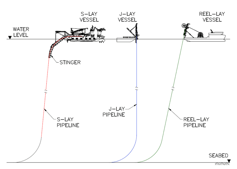
The reel-lay method of pipeline installation is different from the S-lay and J-lay methods of installation as illustrated in Figure 1. Although the reel-lay method of installation appears similar to J-lay, the similarity is only in the sagbend. The J-lay method incurs the least strain during pipelaying as the overbend is eliminated. For reel-lay, the pipe is already bent beyond its elastic limit and then straightened before being subjected to further straining in the sagbend during pipelaying. On the other hand, although there is overbend strain on the pipeline during pipelaying, the residual strain left by the S-lay method of pipelaying is much less than by reel-lay. Therefore, in terms of residual strain, the reel-lay method of installation results in the greatest residual strain on the pipeline and negatively impacts its fatigue life.
Potential Risks & Challenges Associated with Traditional Reel-Lay Operation
Some of the key risks or challenges facing a reeling operation include:
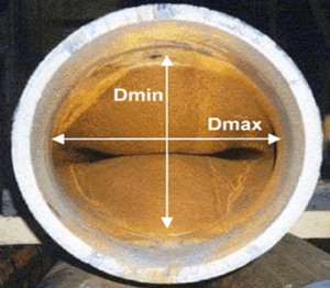
- Increase in pipe ovality caused by reeling (at yard) and un-reeling (offshore). In return, this causes:
-
- Hydrostatic pressure to be greater on flatter sides of the pipe, leading to:
- Potential hydrostatic collapse in deep water.
- Hydrostatic pressure to be greater on flatter sides of the pipe, leading to:
-
- Reduced fatigue life of the pipeline. A plasticised pipe has a lower fatigue life than one installed by other methods that do not result in such high residual strain.
- Mechanical properties of the pipeline are modified, and these include the yield stress, hardening slope and isotropy.
- Critical path risks.
Some of these critical path risks include:
- Weld repairs into storage, i.e., when spooling on the critical path, contractors sometimes have to accept a weld repair as it would be quicker than chopping it out completely. If spooling is off the critical path, a defective weld repair will just be cut off rather than repaired, ensuring that all welds are of high quality.
- Coating damage during stalk handling and/or spooling causes delay in spooling time as the repairs need to be made on the critical path.
- Damage to the field joint coatings during reeling also prolongs spooling time and affects the critical path.
- Risk of critical path welding failures associated with welding one stalk to the preceding stalk which has already been spooled on to the reel while on the critical path of the construction schedule.
- Reel walking, which refers to worker(s) walking on top of the reel as the pipe is being spooled. Working at height in this manner exposes personnel to risks that need to be carefully managed; however, sometimes manual intervention is required to pack out the pipe.
Design & Fabrication Considerations
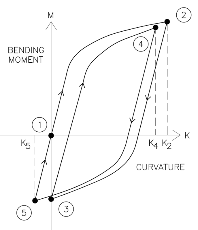
A pipeline used for a reel lay project undergoes a few cycles of plastic deformation. The pipe is first spooled onto a reel drum on a vessel for transportation. During offshore installation, the pipe is unspooled, straightened and laid down onto the seabed. During the process, the pipe is fully and cyclically plasticized. Figures 3 and 4 show the locations where deformations take place during spooling and laying, and Figure 5 shows the plastification cycles undergone by the pipe.
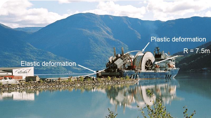
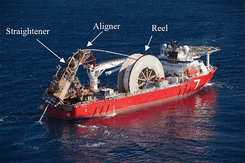
The reeled installation process imposes significant curvature and plastic strain on a pipeline during installation which introduces the requirement of a wall thickness that is sufficient to prevent buckling. The minimum wall thickness is usually in excess of the wall thickness to resist hydrostatic collapses and in-service loading and hence can be the limiting requirement that governs the design.
- When the pipe is reeled onto the reel (1 -> 2) it is largely plasticized, as the non-linearity of the curve shows.
- When the pipe is reeled off and pulled from the reel to the aligner (2 -> 3), its curvature is removed which implies reverse plastification.
- Going into the aligner, the pipe is bent again to a curvature close to the reel one (3 -> 4) leading to a second plastification cycle.
- Finally, the pipe is reverse bent in the straightener (4 -> 5) in order to remove any residual curvature and moment after unloading (5 -> 1).
Figure 5 does not represent the full loading applied to the pipe. The full loading is the sum of a bending driven by the radii of the reel, aligner and straightener, an axial tension driven by the tensioner and contact loads.
Plastification is an irreversible phenomenon that modifies the pipe properties. In this case, it affects the pipeline properties in 3 ways:
- Geometrical shape – reeling and straightening induce some amount of residual ovalisation.
- Mechanical properties – yield stress, hardening slope and isotropy are modified.
- Fatigue properties.
Plastification induces permanent deformation to the pipe in the form of residual ovalisation. Pipe ovalisation is a key parameter for deep water applications. It affects the ability of the pipe to resist collapse under external pressure. The pipe residual curvature is eliminated by accurate straightening. Plastification also modifies the mechanical properties of the pipe. A pipe being plasticized hardens or softens depending on its constitutive materials, and its yield stress is modified. Plastification also modifies the fatigue properties of the pipe.
To account for the punishment received by reeled pipelines, line pipe used for reel lay are generally specified to much higher requirements than other methods, e.g., S-Lay, J-Lay or Tow methods because the pipeline laid via reel-lay is subjected to much more punishment than the other methods. Hence, manufacturing specifications are much more stringent, for example:
- Low thickness fabrication tolerance (D/t ratio)
- Low variation in yield stress
- Low Yield Strength /Ultimate Tensile Strength ratio
- Apply high and steady back tension during reeling
To avoid failure of welds during spooling, unspooling and straightening where the pipeline undergoes plastic deformation, stringent weld requirements are also required to avoid problems with girth welds. One of the measures typically adopted is:
- Over match weld properties to avoid excessive strain in weld
Handling of the pipe during spooling is not an easy operation and special handling care/pre-cautions need to be taken. These include:
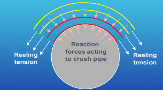
- Care should be taken to ensure that back tension is applied to the pipe when being reeled is not sufficiently high as to crush the pipe layers beneath.
- The reel must be held under tension throughout the reeling-on, transport to site and reeling-off process. This is because the amount of stored energy in the larger reels can be massive and failure of a section that maintains this tension can result in an uncontrolled release of this energy. When this occurs, the pipe will uncontrollably spool itself off the wheel.
For successful reeling operation, the Contractor needs to accurately estimate the followings and ensure that the pipeline is sufficiently strong to withstand these:
- Cumulative strain build-up
- Potential for local buckling
- Resultant ovality
- Crushing
References 1 Ng, E.B. (2019) Subsea Rigid Pipelines – Methods of Installation. Singapore: Partridge.
Dr. Eng-Bin Ng has over four decades of experience in subsea pipeline design and installation and is an experienced and well-regarded industry professional. He has worked for Consultants, Contractors and Operators, and has held design, field, project and managerial appointments. He is a Chartered and Professional Engineer with qualifications in Engineering, Business and Law. He is also the author of the book “Subsea Rigid Pipelines – Methods of Installation”.

